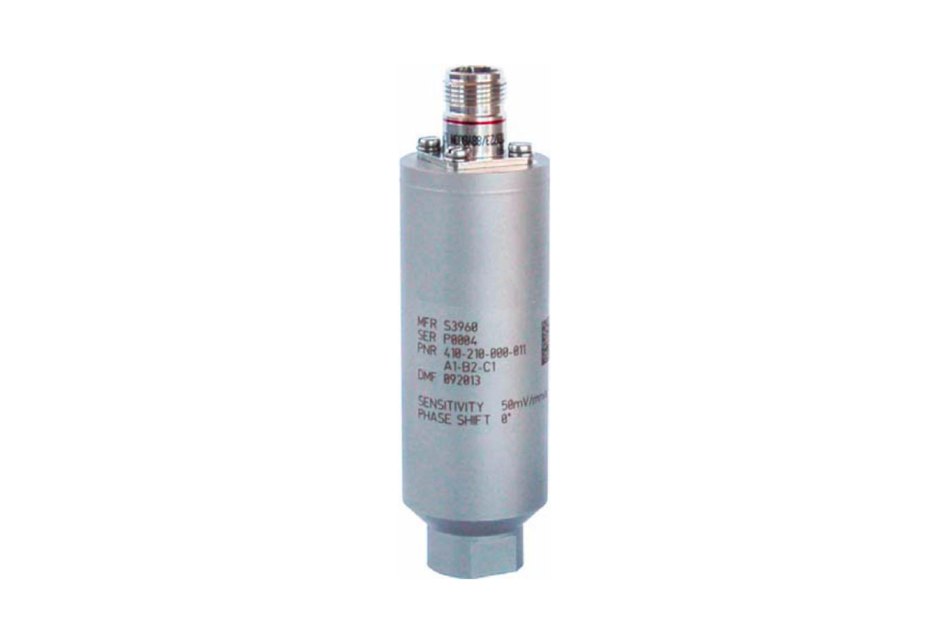
Seismic velocity transducers

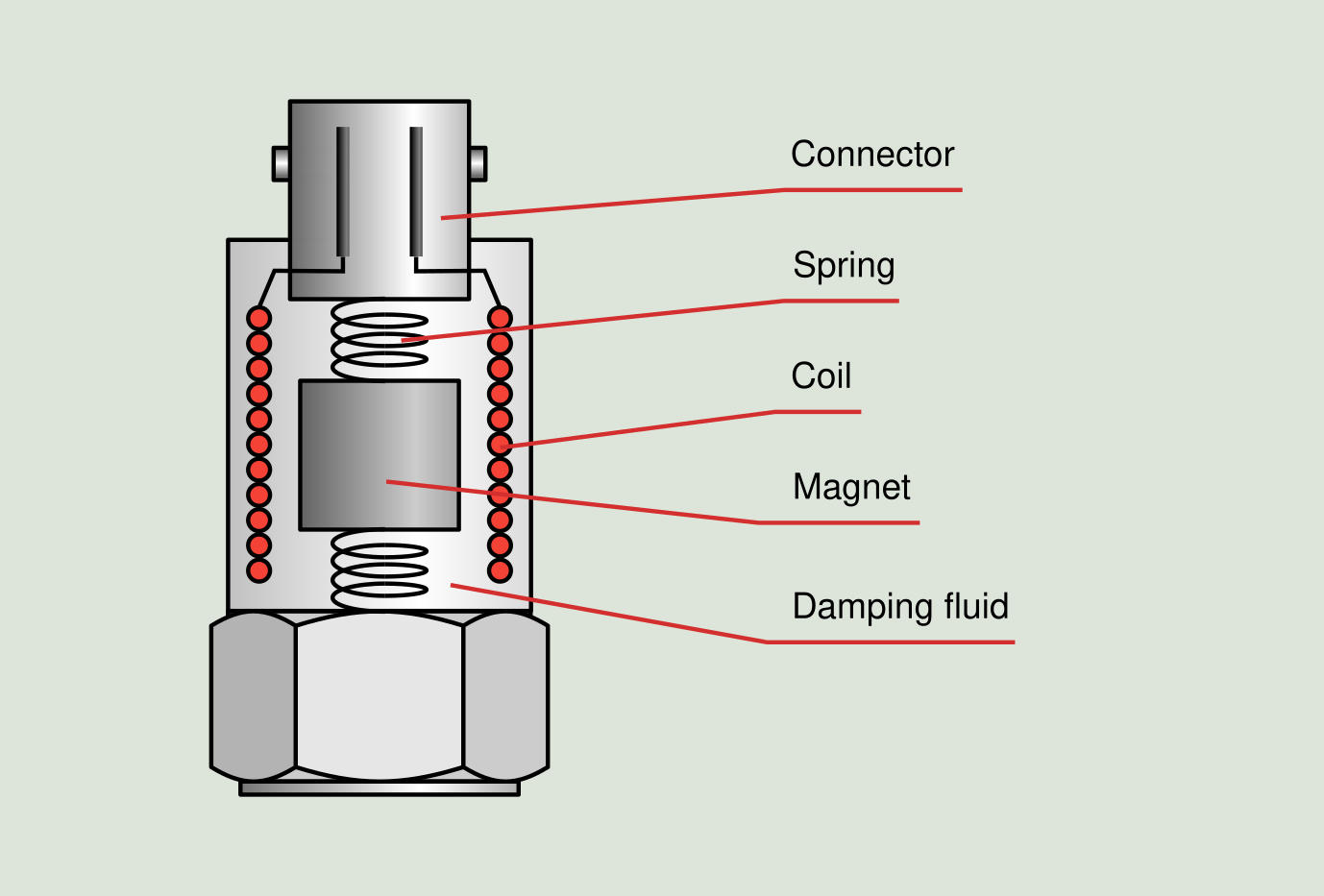
The velocity seismic transducer is used in machines where the shaft transmits vibration to the housing with little damping, ie the vibration amplitudes in the housing are high. It consists of a permanent magnet located in the center of a copper wire coil. When the housing vibrates, a relative movement is created between the magnet and the winding, inducing by the Faraday law a voltage proportional to the speed of movement.
This type of device was developed for its first industrial use in the late 1940s by Arthur Crawford, and its application was extended during the 60s and 70s.
Advantages of the seismic transducer:
- Directly measure velocity, which is proportional to the severity of the vibration.
- No external power supply is required, allowing you to send the electrical signal over long cabling distances by cable, making it ideal for remote permanently installed applications.
- It only requires simple differentiation or integration to convert the signal to other amplitude units. This results on a better quality of data processing.
- They have a very good signal to noise ratio within their frequency range.
Disadvantages of the seismic transducer:
- The dimensions of the transducer are relatively large, requiring large magnetic bases for temporary mounting. Consequently, the frequency range is somewhat limited: 10-1,000 Hz.
- The transducer output varies with temperature. At high temperatures, the output is reduced due to the weakening of the magnetic field. However, specific transducers have been developed for high temperatures.
- The measurement orientation, vertical or horizontal of the transducer can alter the output signal around 5-10%.
- Calibration can be lost due to wear and temperature changes.