Vibration Analysis of Steam Turbines

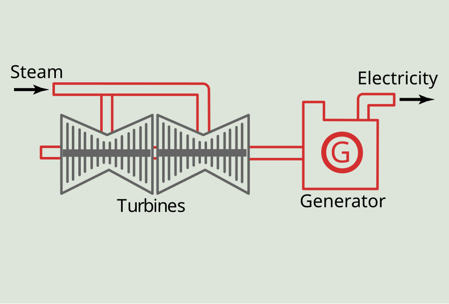
Steam turbines are considered critical auxiliaries for operation in industrial and manufacturing plants. They are primarily used as prime movers for mechanical devices such as pumps, compressors, fans and generators for specific work in the plant processes. The function of a steam turbine is to convert the energy in steam to mechanical energy and used to turn these mechanical devices to produce the specific work desired (Fig. 1).
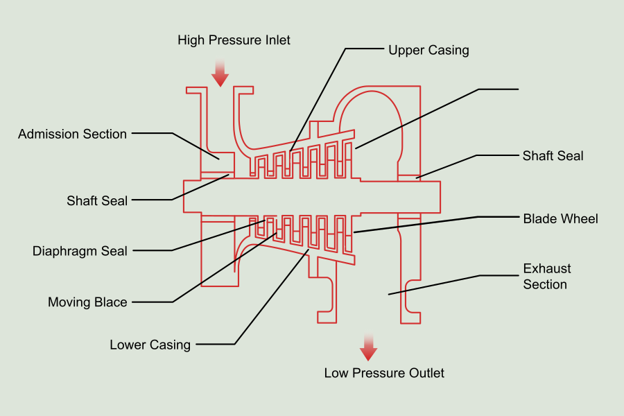
Steam turbines drive these mechanical devices through enormous structures that seem indestructible and are a piece of delicate and precise equipment in a plant. And to operate a turbine safely and efficiently, it is important to have a basic understanding of turbine construction and its operation and methodologies on how it is protected and its behavior adequately monitored during operation (Fig 2.).
The details on the turbine construction and how the different parts work together for its operation will not be part of the discussions in this article. Instead, they will focus on the protection and monitoring systems and diagnosis of anomalies in the machine component. We will also discuss key influencers affecting the component's behavior during operation and analyze the anomalies and indicators of abnormal behavior.
As with other machine components, steam turbines normally encounter different anomalies and abnormal behavior during operation. Most analysts almost always consider these anomalies as a prelude to potential problems that, if ignored and not investigated, usually progress to dangerous situations, if not catastrophic events. Unfortunately, there are numerous cases of catastrophic events in the past on this component when protection and annunciation of an onset of an impending problem are conveniently ignored by few operators and "kick the can" to the next shift, especially during graveyard shifts and no knowledgeable analysts around for help. As a result, no matter how adequately protected and periodically maintained, steam turbines are still vulnerable to anomalies and problems during normal operation.
Establishing the right source of excessive vibration that affects steam turbine operation is probably the most difficult task of machinery analysis. After the source of vibration is determined, it is generally possible to assess the severity of the problem by comparing the vibration level against a specified vibration standard. As the sources of the various excitation forces often occur at different frequencies. It is very useful to characterize measured vibration signals concerning frequency. Thus, spectral analysis is a basic procedure for solving vibration problems and evaluating the reliability of equipment[1].
We should interpret vibration signals obtained from spectral analysis in relation to machine design, installation, and vibration source. Judicious placement of vibration transducers so that a vibration source can be separately identified is necessary to gain maximum use of the vibration criteria. Below is an overview of several most common vibration sources on steam turbines.
 Resonance
Resonance is probably the most common cause of high and vibration-related failures. Unfortunately, vibration specifications often ignore resonances completely and depend upon the manufacturer for such criteria. API standards provide general guidelines on critical speed limits for lateral shaft vibration for several different types of rotating equipment. For example, compressors and pumps must have lateral critical speed limits of 20% above the maximum operating speed or 15% below the minimum operating speed. In addition, amplification factors should not exceed eight while going through critical speeds (Fig. 3). If the measured critical speed falls within the excluded range, then the manufacturer must demonstrate that the vibrations at the critical speed are within acceptable vibration limits with considerably more imbalance than would normally be expected[1].
![Fig. 3: Vibration Rotor Response [1].](https://power-mi.com/sites/default/files/images/blog/fig_3en.png)
Very little can be done to minimize blade vibrations after they have occurred as a problem in the field. The fundamental principle in dealing with blade vibrations is to avoid resonance. The blade's natural frequency should not be within 10% of any identifiable excitation frequencies at any point in the normal operating range, including multiples of blade passage frequency and multiples of running speed. Aerodynamic phenomena are extremely hard to anticipate and vary considerably between machines, and any attempt to operate with an excitation of the lower four or five-blade modes is likely to result in blade loss failure regardless of excitation force monitoring[1].
 Imbalance
Imbalance is a common source of machinery vibrations and is almost always characterized by radial vibration of the shaft or casing, which is in exact synchronization with rotor speed (Fig. 4).
![Fig. 4: Spectral characteristic of Imbalance [1].](https://power-mi.com/sites/default/files/images/blog/fig_4en.png)
Rotor imbalance is a condition of unequal mass distribution of each radial section of the rotor. In an unbalanced condition, the rotor mass centerline does not coincide with the axis of rotation. During rotation, rotor unbalance generates a centrifugal inertia force which rotates at the rotor rotational frequency. Imbalance represents the first fundamental mechanism to transfer the rotational energy into vibrations[2].
Unavoidable geometry imperfections due to fabrication or material variation will result in rotor imbalance such that virtually all new high-speed machines will require balancing at the factory. Some very sensitive machines will also require rebalancing after installation. Vibration should be expected to change gradually with time as the effects of erosion, wear, and particle adhesion act to change the imbalance. Rotor parts such as thrust collars, cooling fans, and coupling hubs may be significant sources of imbalance but are often overlooked because of their low amplitude. A careful correlation of vibration with thermal shaft growth is necessary to identify these sources of variable imbalance[1].
The sub-synchronous response vector locus is usually presented in Bode or Polar plot formats. The rotor vibration signal is filtered to the frequency of the rotation and is usually compensated by subtracting the slow roll (low frequency) 1 X response vector. These formats are widely used for unbalance diagnosis and correction (Fig. 5). The plots also allow for easy detection of resonant frequencies., and evaluation of the system's effective damping and synchronous amplification factor using the half-power bandwidth method[2].
![Fig. 5: Bode and polar plots of a machine rotor 1X filtered response measured by a vertical displacement transducer. These formats help to identify the first balance resonance frequency, and the unbalance (heavy spot) location [3].](https://power-mi.com/sites/default/files/images/blog/fig_5en.png)
Rotor imbalance is normally corrected by machine balancing routine procedures, which can be performed by balancing software programs widely used by most diagnosticians. The procedure can also be made using a graphical presentation of influence coefficient vectors when balancing software programs are unavailable.
 Fluid Induced Instabilities
The rotating shaft operates in a fluid environment. An interaction between the rotor and the surrounding fluid becomes significant if the clearances between rotating and stationary parts are small and the rotor operates in low eccentricity within the clearances. Due to friction, shaft rotation generates a circumferential flow of the fluid. The fluid in turn produces a dynamic effect of rotating forces acting in feedback to the rotor. Such situations occur in lightly loaded fluid-lubricated bearings, seals in balance pistons, stator/blade clearances, and rotor/stator peripheries. Similar phenomena occur in all cases where the fluid becomes involved n rotational motion, such as in centrifuges, rotors with trapped fluid or rotors filled with fluid. Well-known are the final dynamic effect of such rotor/fluid interactions, namely, the rotor self-excited sub-synchronous vibrations of the “fluid whirl” and “fluid whip” types[1]. Instabilities usually exhibit vibration frequencies at about 1/2 running speed (Fig. 6) and have a. tendency to increase suddenly in amplitude with disastrous results.
![Fig. 6: Spectral Characteristics of Subsynchronous Instabilities [1].](https://power-mi.com/sites/default/files/images/blog/fig_6en1.png) The diagnosis of fluid whirl/whip vibrations is relatively easy, especially when the transient startup/shutdown data are available. The filtered whirl/whip phase measurements allow identification of the location of the instability source along the machine train. More difficult, however, is the identification of what actually causes instability, especially when only the whip vibrations are present[2].
The diagnosis of fluid whirl/whip vibrations is relatively easy, especially when the transient startup/shutdown data are available. The filtered whirl/whip phase measurements allow identification of the location of the instability source along the machine train. More difficult, however, is the identification of what actually causes instability, especially when only the whip vibrations are present[2].
Shaft centerline position data may indicate impending fluid-related malfunction earlier that the actual appearance of whirl/whip vibrations. A gradually decreasing eccentricity position of the journal inside the bearing clearance due to either change in radial load forces or due to bearing surface wear warn that fluid whirl or whip mat soon occur. Axial vibrations and position data may also warn about changes in flow which may lead to whirl/whip vibrations (Fig7)[2].
![Fig. 7: Spectrum cascade of the rotor vibration exhibiting fluid whirl and whip of the first two modes. Shaft rotates concentrically in one bearing bushing the other one oil-lubricated bearing [3].](https://power-mi.com/sites/default/files/images/blog/fig_7en1.png)
 Misalignment
Excessive misalignment of rotating elements driven through flexible couplings is usually indicated by a large second-order vibration component (Fig. 8).
![Fig. 8: Spectral Characteristics of Misalignment [1].](https://power-mi.com/sites/default/files/images/blog/fig_8en.png) Occasionally, large first-order vibrations are also observed. High axial vibration is another indication that misalignment is likely. Shaft operating misalignment is affected by relative thermal growth, static forces applied by piping or condenser attachments, deterioration of support grouting, etc. Vibration due to first-order misalignment can be differentiated from imbalance by recording vibration in relation to rpm. Imbalance vibration will increase with the rpm squared, while misalignment vibration will not change if resonances are not involved. For machines that cannot be conveniently shut down, a record of the vibration spectrum should be recorded when the machine is first started up and in good alignment. This can be used for later comparison to determine if the alignment of the machine is still satisfactory[1].
Occasionally, large first-order vibrations are also observed. High axial vibration is another indication that misalignment is likely. Shaft operating misalignment is affected by relative thermal growth, static forces applied by piping or condenser attachments, deterioration of support grouting, etc. Vibration due to first-order misalignment can be differentiated from imbalance by recording vibration in relation to rpm. Imbalance vibration will increase with the rpm squared, while misalignment vibration will not change if resonances are not involved. For machines that cannot be conveniently shut down, a record of the vibration spectrum should be recorded when the machine is first started up and in good alignment. This can be used for later comparison to determine if the alignment of the machine is still satisfactory[1].
Excessive misalignment due to radial loads can be diagnosed from the vibration data. Abnormal orbital motion, abnormal radial average shaft centerline and abnormal shaft versus casing motion indicate excessive radial loads. Figure 9 shows the plots that illustrate misalignment characteristics and excessive radial preloads on the rotor. A continuously acting radial preload on a rotor operating at a constant speed causes periodic 1X frequency (plus possible higher harmonics) reversal stresses on the rotor fiber. This condition may lead to rotor cracking and premature failure[2].
![Fig. 9: Excessive Radial Load /Misalignment Diagnosis: frequency, spectra, orbits and centerline position [2].](https://power-mi.com/sites/default/files/images/blog/fig_9en.png)
 Rub
Rub
Rubbing between the rotor and the stationary part of the machine is a serious malfunction that leads to a catastrophic failure. Rubbing involves several physical phenomena, such as friction, stiffening coupling effect, impacting, and may affect the machine system's solid/fluid/thermal balance. Rubbing always occurs as a secondary effect of a primary malfunction, such as unbalance, misalignment, or fluid-induced, self-excited vibrations, which result in high lateral vibration amplitudes and or change in the shaft centerline position within available clearances[2].
Rubs between a rotor and close clearance stationary components can cause damage to seals and blade tips. The reported characteristics of rub-induced vibration include fixed rotor subharmonics, sub-synchronous vibration at a natural frequency, super-synchronous vibration at a natural frequency, time-varying synchronous vibrations, and vibration at multiples of running speed. Thus it is difficult to make general statements about rubs, and the materials influence the symptoms of rubbing in contact, the impedance to the motion of the seal when contacted, the location of natural frequencies, etc. Rubs of stainless steel rotors appear particularly damaging and are known to cause rapid, permanent rotor deformation. On the other hand, high-performance steam turbines are designed with very tight labyrinth clearances and are almost expected to rub mildly during the early stages of commissioning. These quick rubs can cause localized heating and a temporary bow in the rotor, with associated high imbalance, particularly when the rotor runs below its first critical speed. The symptoms of this particular rub-induced vibration are a slow time variation of synchronous amplitude and phase, and often a square-like orbit (Fig.10)[1].
![Fig. 10: Shaft Orbit for Rub Induced Synchronous Vibration [1].](https://power-mi.com/sites/default/files/images/blog/fig_10.png)
The diagnosis of rotor rubbing from vibration data is based on (i) the appearance in rotor synchronous response vectors, (ii) the appearance of sub-synchronous fractional components which when filtered, most often exhibit backward orbiting, (iii) short lasting appearance of continents with natural frequencies (due to transient character of rubbing), (iv) appearance of higher harmonics of the fundamental components, (v) changes in shaft centerline position (Fig 11). Partial or fully backward orbiting of the rotor is the most characteristic for rubs, distinguishing this malfunction from the others [2].
![Fig. 11: Rub diagnosis in a turbogenerator: shaft centerline as function of load; orbit, timebase waveform, and spectrum of 50MW and 3600 rpm. The presence of rub-induced 1/2 X subsynchronous vibrations [3].](https://power-mi.com/sites/default/files/images/blog/fig_11en.png)
There are of course other sources of vibration other than those discussed above, which can cause machine failure. Mention a few are: mechanical looseness of the shaft and stationary parts, coupling shifts, looseness between the rotor supporting pedestal and foundation, oversize and poorly lubricated bearing, excessive clearance in rolling element bearings, defective rolling element bearings, noise which is produced by faulty gears, etc.
Vibration Measurements And Basic Parameters
As mentioned earlier, though massive in structure and seem indestructible, turbines are delicate components in a machine configuration that need adequate protection and monitoring of vibration behavior for trouble-free operation. Although preventative maintenance has proven to be beneficial in terms of increasing productivity and lowering unscheduled downtime, condition-based maintenance has demonstrated that applying condition monitoring leads to better machinery reliability than time-based maintenance (preventive maintenance).
This condition-based maintenance philosophy is successfully applied where the rotating machinery component represents the limiting factor in a system, such as steam turbines. Obviously, this type of predictive maintenance program requires dependence upon instrumentation and the proper interpretation of the data it provides. All available parameters of vibration and rotor position are important to be measured and evaluated. A simple investigation of amplitude and frequency alone does not provide sufficient information about machinery performance to provide a strong and accurate diagnosis.
Parameters
The following is a discussion of basic dynamic motion (vibration) and rotor position parameters that should be measured and analyzed in the diagnosis of rotating machinery in predictive maintenance programs:
Dynamic Motion (Vibration)
- Amplitude
Amplitude, whether expressed in displacement, velocity, or acceleration, is generally an indicator of the severity of the anomaly. It attempts to answer the question, "Is this machine running smoothly or roughly?" The dynamic motion in steam turbines is best monitored and protected using proximity probes installed in orthogonal orientation to observe shaft dynamic behavior. The ability to measure the shaft with proximity probes has helped greatly in providing more accurate information with regard to the amplitude of vibration. In the past, casing measurement employed only provided vibration amplitude as an available parameter for severity and indicates the presence of machinery malfunction. The measurement, however, proved inadequate for proper machinery protection. This was primarily due to the variable transfer impedance between the shaft and casing motions, depending upon the particular machine design, assembly, operating condition, and case pickup location.
The amplitude of vibration is expressed in peak-to-peak mils displacement. With proximity probes mounted at or near the bearings, vibration tolerances can be established, which provide for the maximum excursion the shaft makes to the bearing. A normal operating machine will generally have a stable amplitude reading of an acceptable low level. Any change in this amplitude reading indicates a change in the machine condition and should be considered justification for further investigation of the particular machine condition.
- Frequency
Frequency is an important piece of information with regard to analyzing rotating machinery and can help to classify malfunctions, but it is only one piece of data. The frequency of vibration (cycles-per-minute) is most commonly expressed in multiples of rotative speed of the machine. This is primarily due to the tendency of machine vibration frequencies to occur at direct multiples or sub-multiples of the rotative speed of the machine. It also provides an easy means to express the frequency of vibration. It is necessary only to refer to the frequency of vibration in such terms as one times rpm, two times rpm, 43% of rpm, etc., rather than having to express all vibrations in cycles-per-minute or hertz.
It is extremely important to note, however, that the frequency/malfunction relationship is not mutually exclusive. That is to say, a vibration at one particular frequency often as more than one malfunction associated with it. There is no one-to-one relationship between malfunctions and frequencies of vibration. One must not be easily swayed into attempting to directly correlate certain frequencies with particular specific malfunctions. It is necessary to evaluate all data before arriving at a conclusion.
The typical means of expressing frequency is as follows:
It is important to note a mean differentiating two types of vibration: Synchronous and non-synchronous. Synchronous vibration occurs at a frequency which is some direct multiple or integer fraction of rotative speed of the machine. Basic frequency measurements can be made with the use of a Keyphasor and an oscilloscope. It is possible, with some minimal practice, to be able to pick out the major components of vibration present in a vibration waveform.
- Phase Angle
The phase angle of vibration has long been ignored as an important criterion for the analysis of rotating machinery by people in many areas of rotating machine use. Sensible people in the power generation and oil & gas industries, however, long recognized its value. The phase angle measurement is a means of describing the location of the rotor at a particular instant in time. A good phase angle measuring system will define the location of the High Spot of the rotor at each transducer location relative to some fixed point on the machine train. By determining these High Spot locations on the rotor, it is possible to determine the balance condition and locations of the residual unbalances on a rotor. Accurate phase angle measurements are extremely important in the balancing of rotors and can be extremely important in the analysis of particular machine malfunctions. The phase angles of the rotor as determined by various transducers along a machine train can provide valuable information as to the performance of the machine train. It is this phase angle that provides timing information that helps answer the questions: What is happening, where, when, and how?
The phase angle is also valuable in determining the rpm location of the natural rotor balance resonance (“critical"). The most accurate and reliable means of measuring phase angle is with the use of a Keyphasor (shaft reference). The measurement rapidly gained acceptance as a very important parameter for the diagnosis of rotating machinery as well as for balancing operations and is generally included as part of the instrumentation package for large steam turbines in power generation service and driving mechanical devices such as compressors, pumps, and fans.
- Vibration Form
The form of the vibration is perhaps the most important means of presenting vibration data for analysis. It is through this type of presentation that an understanding of a particular machine's behavior can be realized. The previously discussed three parameters have all been measurable quantities that can be displayed on an indicating meter or digital display, while "vibration form" is the raw waveform itself, displayed on an oscilloscope or in modern times with a computer software program. Vibration form can be separated into two separate categories: (1) Time Base presentation; and (2) Orbital presentation. Time Base presentation is provided by displaying transducer inputs on the oscilloscope/software program in the time base mode. In this mode, the sinusoidal type waveform is displayed representing the shaft relative to the input transducer versus time horizontally across the reference point. In this mode, the oscilloscope/software program displays the centerline motion of the shaft at that horizontal location along the rotor. If the probes are mounted at the bearing, the orbit is a presentation of the motion of the shaft centerline in relationship to the bearing.
These two presentations give diagnosticians/engineers the most data in one presentation. Basic amplitude, frequency, and phase angle can be determined by viewing the vibration form. The vibration form presentations inherently help the individual to understand "what the machine is doing”, by observing the actual motion of the observed part. This is an important concept. The vibration form allows for the transition from determining what the amplitudes and frequencies are, to determining "What The Machine Is Doing". This is the ultimate parameter that we are attempting to measure in any preventive or predictive maintenance program.
- Vibration Mode Shape
A recommended practice for providing information on a rotating machine is to provide an extra set of X-Y (90o apart) probes some distance away from the bearing. These extra-horizontal probes would not normally be monitored but would be available for diagnostics. The extra-horizontal set provides a third dimension to the machinery data. It allows for an estimate of the mode shape of the machine rotor for the determination of nodal points. It is important to recognize that any set of X-Y probes along the machine train will provide the motion of the rotor at that horizontal location along the machine. Therefore, by utilizing the extra set of X-Y probes at a different horizontal location along the machine train, we can attempt to determine the basic mode shape of the rotor itself. This mode shape can help to give closer estimates of the internal clearances between the rotor and stator elements and estimate the nodal points along the rotor shaft.
Position Measurements
Other parameters that should also be measured and evaluated for total machinery performance fall under static or quasi-static position measurements. Depending upon the particular machine design and machine malfunction, these measurements can be important in evaluation and analysis. The following provides a discussion of these position-type measurements:
- Eccentricity position
Eccentricity position is the measurement of the steady state position of the shaft in the journal bearings. Under normal operation with no internal or external preloads on the shaft, the shaft of most machine designs will ride where the oil pressure dam places it. However, as soon as the machine gets some external or internal type preload (steady state force), the eccentricity position of the shaft in the journal bearing can be anywhere. Therefore, this eccentricity position measurement can be an excellent indicator of bearing wear and heavy preload conditions such as misalignment.
Eccentricity position should also be closely watched during machine start-up. For example, during a machine start-up with a vertically mounted proximity probe, one would normally expect the shaft to rise from the bottom of the bearing to some place toward the center of the bearing. This is due fundamentally to the oil flowing under the shaft making the shaft rise in the bearing. It is generally believed that the oil film is about one mil in thickness. However, observations on many bearings show that it is more often about 1/3 of the bearing clearance in the preloaded direction of the shaft.
The proximity probe transducer system must have a long linear range sufficient to allow these eccentricity position changes to occur without having the shaft move outside of the linear range of the proximity probe. This is especially true in large machines with large bearing clearances. Therefore, it is important to document the cold and hot eccentricity positions so that a frame of reference is established for comparisons of eccentricity positions at later dates.
- Axial thrust position
Axial thrust position measures the relative position of the thrust collar to the thrust bearing. This measurement is perhaps one of the most important monitored parameters on a steam turbine and/or centrifugal compressor. The primary purpose of an axial thrust position monitor is to ensure against an axial rub between the rotor and the stator. Axial thrust bearing failures can be catastrophic, and every attempt should be used to protect against this possible machine failure mode.
At least one, preferably two, axial thrust position probes should be mounted to provide axial thrust position protection. Care must be taken in the selection of probe mounting locations to ensure the minimum effect of thermal growth of the rotor and the minimum effect of the springiness of the thrust bearing assembly in the accuracy of the reading. In early applications of proximity probes for axial thrust position measurements, it was very often found that the alarm and danger set points were established too close to the initial cold float zone of the machine. It was found that deflections occur in the thrust bearing assemblies and thermal growth of the rotor occurs such that under normal operating conditions, the rotor's position can appear to be wider than the normal cold float zone of the rotor within its thrust bearing. It is important to note that most machines have sufficient axial clearance between the rotor and the stator that wide set points can be established, allowing the thrust collar to severely wipe the babbitt of the thrust bearing shoes without having rotor to stator rubs. Under normal operating conditions of centrifugal compressors or steam turbines, thrust position can vary with the machine's load, so varying thrust position measurements under differential loads and conditions of a machine are not uncommon. The thrust position measurement may also be important in the determination of surge of incipient surge conditions.
If axial vibration is to be monitored or used for the diagnosis of a particular machine it is necessary for the observed surface to be smooth and to be perpendicular to the centerline of the rotor. This will minimize any effect of mechanical runout of the dynamic output of the probe, thus providing accurate axial vibration readings.
- Eccentricity Slow-Roll (Peak-To-Peak Eccentricity)
In large steam turbines for power generation service and in some industrial gas turbines, it is very often desirable to indicate eccentricity slow-roll, also called peak-to-peak eccentricity. Eccentricity slow roll is the amount of bow the rotor takes when it is at rest (turning gear condition). The slow-changing dc peak-to-peak measurement can indicate this bow from the proximiter as the rotor turns on turning gear. When the peak-to-peak amplitude is at an acceptable low level, the machine can be started without fear of damage to seals and/or rotor rubs caused by the residual bow and its corresponding unbalance. Eccentricity slow-roll is best measured with a probe mounted away from the bearing (or at the end of the machine train) so that maximum bow deflections can be measured.
- Differential Expansion
In large machines such as large steam turbines in power generation service, it is extremely important that the casing and the rotor grow thermally at the same rate during start-up. If the rotor or the casing grows at different rates, there exists the possibility of damage to the machine caused by axial rubs. To measure this differential expansion, a proximity probe is mounted at the end of the machine opposite the thrust bearing where the relative growth between the case and the rotor can be observed. The typical range for this proximity probe is 1 inch. However, in very large machines, this range required of the proximity probe system can be as great as 2 or 3 inches.
- Case Expansion
On a large machine, it is also very common to provide a case expansion measurement in addition to the differential expansion. This case expansion measurement is usually provided by a contacting linear variable differential transformer (LVDT) mounted externally to the machine case and referenced to the foundation. This case expansion measurement helps to provide information about the relative growth of the rotor to the case, as described in the section on differential expansion. Knowing the amount of case growth and differential growth makes it possible to determine which is growing at a more rapid rate - the rotor or the case. If the case is not growing properly, the "sliding feet" of the case may be stuck.
Other Parameters
-
Speed (rpm)
The measurement of the speed (rpm) of the rotor has long been standard procedure. Most major centrifugal machine trains have been continuous indications of the machine's rpm. With the advent of new, reliable digital circuitry, digital tachometers have become more popular for speed indication. Besides being more accurate and easier to read, the digital tachometer lends itself very well to providing redundant overspeed trip protection. The digital rpm indication eliminates many older problems associated with rpm measurement. An accurate, readable rpm indication is generally provided in the control room for operators to observe.
Transducer inputs for the digital tachometers can be from a variety of inputs. Among the more popular are the Keyphasor proximity probe input, the photo electrical pickup, and magnetic pickup. These transducers are all designed to observe several events per revolution of the shaft. This digital input is then translated into a direct rpm readout using the digital tachometer circuitry.
The correlation of vibration measurement with rpm can be important for the final analysis of the mechanical performance of a particular machine. Centrifugal equipment is designed to operate in a speed range that will not coincide with the balance resonance of that particular machine and at speeds that will not excite this particular resonance. A start-up piece of information that is important for determining the balance resonance is an X-Y plot of the amplitude and phase angle of the vibration vs. rpm of the machine. In plotting and correlating these parameters, it is possible to determine the machine balance resonance (critical) easily.
- Temperature Measurement
Other parameters also become important in the final analysis of the condition of a particular piece of rotating machinery. Temperature measurements are one of the most popular and important parameters not yet discussed. The temperature of the bearing babbitt in both radial and axial bearings is becoming more and more popular. The correlation of this temperature information with vibration and/or position measurements helps to indicate possible machinery malfunctions better.
- Correlation
Correlation of temperatures, pressures, flow, and other external parameters which could affect the operation of a piece of machinery is extremely important for the overall system analysis of the machine in service. It is through this correlation that a good predictive maintenance program can be established. The ability of the engineer to utilize all of the available information in determining the mechanical running condition of the piece of machinery is extremely important in maintaining proper operation and continuous online service of any piece of equipment.
An engineer who thoroughly understands the parameters discussed in this paper will have a good beginning toward understanding the mechanical performance of centrifugal equipment. Through understanding these parameters, he will ultimately be able to determine "what a particular piece of machinery is doing."
[1] More Comprehensive Vibration Limits for Rotating Machinery, ASME 86-GT-148 - A. Lifshits, H. R. Simmons, A. J. Smalley.
[3] Bently Nevada Mechanical Diagnostics Services (MDS) Reports 1987-1990.
What is Power-MI?
Power-MI is a cloud based solution that allows you to design & manage your condition-based maintenance plan integrating all techniques into one platform. Easy reporting, automatic work orders and CMMS integration.
Read more